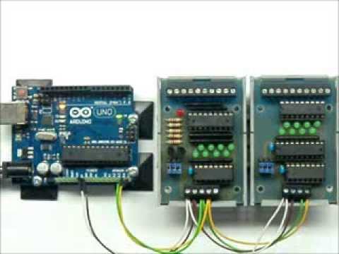
Im nachfolgenden Beispiel werden 8 Bit vom I2C-INPUT-Modul gelesen und 1:1 auf das I2C-OUTPUT-Modul ausgegeben.
Es ist also damit möglich mehrere digitale Signale von einer Karte auf die andere zu übertragen.
Die Adressierung der beiden Karten ist in der zweiten und dritten Zeile programmiert. Die auf unseren Karten aufgedruckte Adresse ist die 8-Bit Adresse. Beim Arduino muss die Slaveadresse im 7-Bit Format angegeben werden. Deshalb wird die Adresse mit dem Befehl >> 1 durch zwei geteilt.
In den nächsten Programmzeilen werden alle Bits der Eingangskarte im PCF8574A nach high gesetzt. High ist auch die Grundeinstellung des PCF8574(A) wenn er an die Versorgungsspannung angeschlossen wird.
/*
 ==============================================
 Test I2C-Input auf I2C-Output
 ==============================================
 */

#include <Wire.h>
#define I2C_IN_ADDR 112 >> 1 // I2C-INPUT-Addresse als 7 Bit
#define I2C_OUT_ADDR 64 >> 1 // I2C-OUTPUT-Addresse als 7 Bit

byte WERT=0;
byte OUT_INV=0;
byte ALTWERT;

void setup() {
  Serial.begin(9600);       // Serielle Schnittstelle konfigurieren
  Wire.begin();             // I2C-Pins definieren

  // setzten aller Bits der Eingabekarte auf 1
  // -----------------------------------------
  Wire.beginTransmission(I2C_IN_ADDR);   // Start Übertragung zum PCF8574
  Wire.write(0xFF);                      // Alle Bits sind Eingänge
  Wire.endTransmission();                // Ende
}

void loop() {

  // Einlesen der Bits aus der I2C-INPUT Karte
  // ------------------------------------------
  Wire.requestFrom(I2C_IN_ADDR, 1);    // Ein Byte (= 8 Bits) vom PCF8574 lesen
  while(Wire.available() == 0)         // Warten, bis Daten verfügbar
    ;
  WERT = 255 - Wire.read();            // in invertierte Eingabe wandlen

  if (WERT != ALTWERT) {               // Wert nur ausgeben wenn er sich ändert
    Serial.print("neuer Wert: ");
    Serial.println(WERT);              // Wert auf "Seriel Monitor" ausgeben
    Wire.endTransmission(true);
    ALTWERT=WERT;                      // und nachführen
  }

  // Ausgeben der gleichen Bits an die I2C-OUTPUT Karte
  // --------------------------------------------------
  OUT_INV = 255 - WERT;                 // in invertierte Ausgabe wandlen
  Wire.beginTransmission(I2C_OUT_ADDR); // Start Übertragung zum PCF8574
  Wire.write(OUT_INV);                  // Wert schreiben
  Wire.endTransmission();               // Ende

}


Hello,
I recently purchased a I2C input module. Before trying it out I have a question about the pull-up resistors you mentioned in previous post. When are they needed? Because they are not on the pictures of this blog.
I intend to use this I2C input module with a controllino mega PLC which uses a ATmega 2560-16AU as processor. https://www.controllino.com/product/controllino-mega/
I could try with or without the pull-up resistors, but i’m afraid to damage the plc or input board.
Thanks!
=====================================
Hallo,
Ich habe vor Kurzem ein I2C-Eingabemodul gekauft. Bevor ich es ausprobiere, habe ich eine Frage zu den Pull-Up-Widerständen, die Sie im vorherigen Beitrag erwähnt haben. Wann werden sie benötigt? Weil sie nicht auf den Bildern dieses Blogs zu sehen sind.
Ich beabsichtige, dieses I2C-Eingabemodul mit einer Controllino Mega-SPS zu verwenden, die einen ATmega 2560-16AU als Prozessor verwendet. https://www.controllino.com/product/controllino-mega/
Ich könnte es mit oder ohne Pull-Up-Widerstände versuchen, aber ich habe Angst, die SPS oder die Eingabeplatine zu beschädigen.
Danke!
Hallo Thomas,
leider finde ich in der Dokumentation nichts über die I2C-Leitungen SDA und SCL.
Kannst du mal mit einem Messgerät die Spannung an SDA gegen GND und SCL gegen GND Messen. Wenn hier 5V anliegen, sind intern Pullup-Widerstände verbaut. Wenn nicht, bitte zwei 4,7k oder 10k Widerstände von SDA nach +5V und von SCL nach +5V einbauen.
keine Angst, selbst wenn intern Widerstände eingebaut sind, kann nichts kaputt gehen.
Gruß, Jürgen
=====================================
Hello Thomas,
Unfortunately I can’t find anything in the documentation about the I2C lines SDA and SCL.
Can you use a measuring device to measure the voltage on SDA against GND and SCL against GND. If there is 5V here, pull-up resistors are installed internally. If not, please install two 4.7k or 10k resistors from SDA to +5V and from SCL to +5V.
Don’t worry, even if resistors are installed internally, nothing can break.
Best wishes, Jürgen
Thanks for the fast reply.
I measured 5V on SDA and SCL, so I tried without the pull up resistors. It works great! Although it took me a while to figure out that I ordered the PCF8574A so I had to use address 112 instead of 64. But after fixing this everything works great!
I am using A4 for SDA and A5 for SCL.
I will try connecting resistors.
Thanks and Regards
Nithin
Thank you so much for your reply, I am using PCF8574 for output module and PCF8574A for input module but i also tried with PCF8574 for both the modules but still it did not work, what could be the problem?
Thanks and Regards
Nithin
Hello,
witch Pins did you use on the arduino?
please make a resistor 4,7k or 10k between
+5V and SDA
and an second resistor 4,7k or 10k between
+5V and SCL
Hello,
I tried the code with arduino uno, but the code is not working for me, is it something has to do with input and output addressing pins i am using 8574 and in the input board it shows 64 +1(65), can you please help me.
Thanks and Regards
Nithin
Hello,
both modules with PCF8574?
Then you have to Jumper the Output-Board LOW LOW LOW = slave-address 64
and the Input-module LOW LOW HIGH = slave-address 66
#define I2C_IN_ADDR 66 >> 1 // I2C-INPUT-Addresse as 7 Bit#define I2C_OUT_ADDR 64 >> 1 // I2C-OUTPUT-Addresse as 7 Bit
Then it works